
Bed leveling system
Automated bed mesh leveling: a probe attached to the extruder maps the bed surface at multiple points to compensate for unevenness during the first layer.
Function
Section titled “Function”- Probes the bed at a grid of points
- Generates a height map (mesh) used during printing
- Compensates for bed warping, frame flex, and non-flat surfaces
- Combined with the Z offset, produces a perfect first layer
Components
Section titled “Components”| Part | Purpose |
|---|---|
| Probe | A switch lowered by a small servo motor. The servo drops the switch during probing and lifts it again as soon as probing finishes. When down, the switch acts as both endstop and probe |
| Probe arm (E21) | The 3D-printed arm that carries the switch, mounted on a factory-calibrated metal arm. When replacing the printed arm, do not remove the metal arm it attaches to |
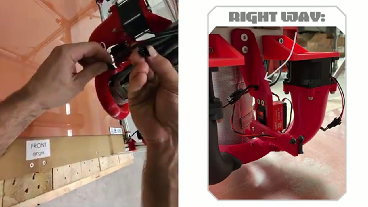
| Servo connector | A black 3-pin JST connector links the servo to the board behind the extruder — a frequent fault point (see Probe arm bending) |
| Probe cable | Signal to MCU; sensitive to bends and disconnects |
| Bed surface | Tempered glass (standard); some customers use a fibreglass plate — see Bed surface |
Before homing or leveling — clean the nozzle
Section titled “Before homing or leveling — clean the nozzle”Recovering after a crash / to raise the gantry: tap Home Z a few times. Each tap performs only the gantry raise that precedes homing, without actually running the Z home — this lifts the gantry away from the bed safely. Then clean the nozzle and re-run the bed calibration (follow the Ginger bed-leveling video).
How it works
Section titled “How it works”- Bed leveling macro starts
- Printer homes XY
- Probe descends at each grid point and records Z height
- Mesh saved to firmware
- During printing, the firmware adjusts Z per the mesh
Running a bed leveling
Section titled “Running a bed leveling”The correct path on the display is More → Bed Level (not just the Macros menu).
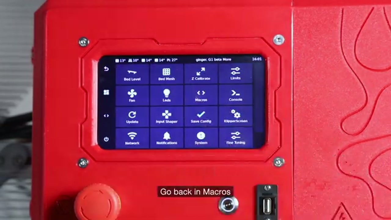
The More menu on the display contains: Bed Level, Bed Mesh, Z Calibrate, Limits, Fan, Leds, Macros, Console, Update, Input Shaper, Save Config, KlipperScreen, Network, Notifications, System, Fine Tuning.
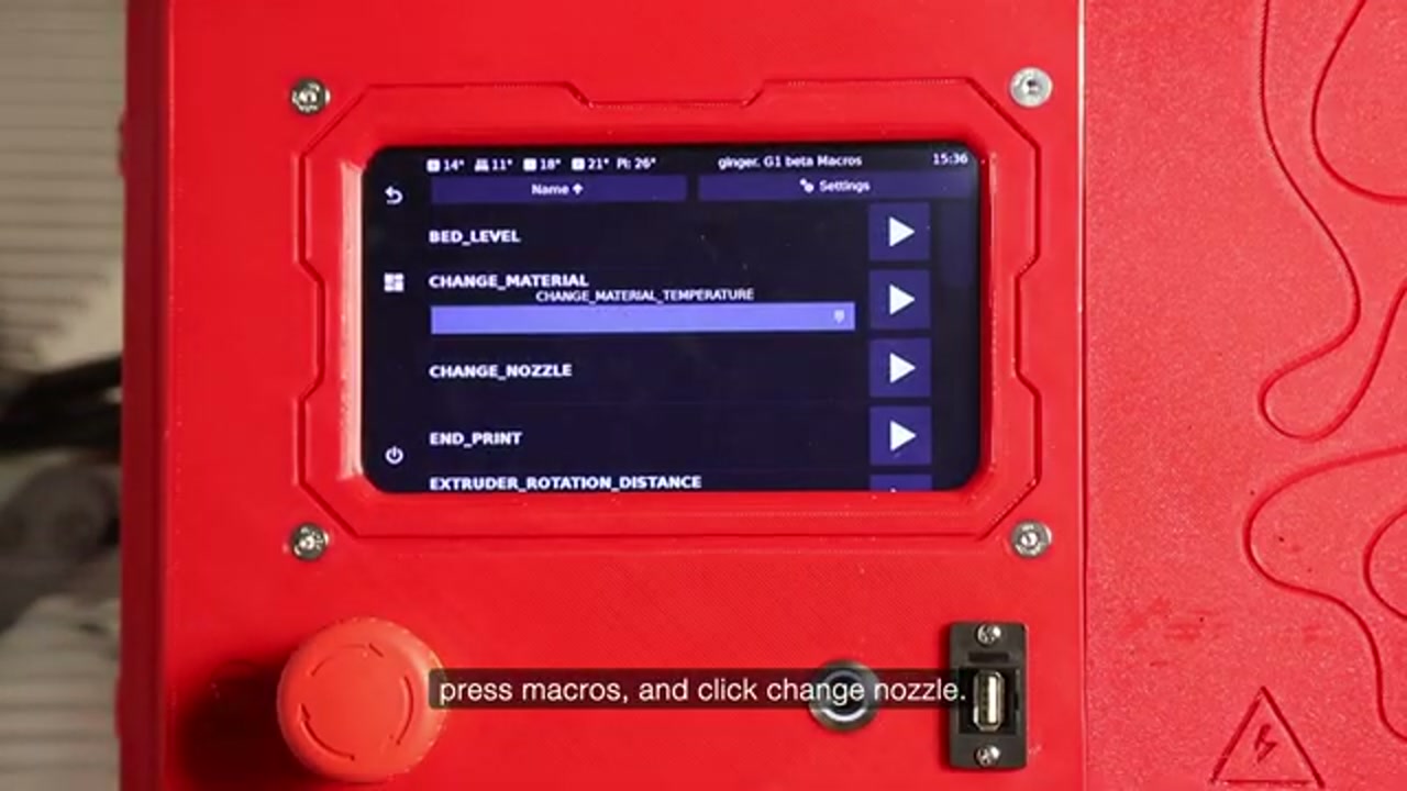
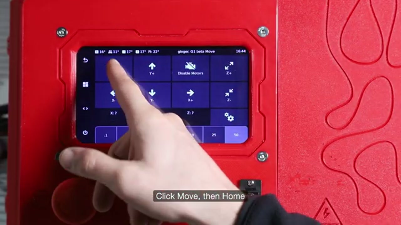
- From the printer display, open More → Bed Level
- Wait for all points to be probed (1–3 min)
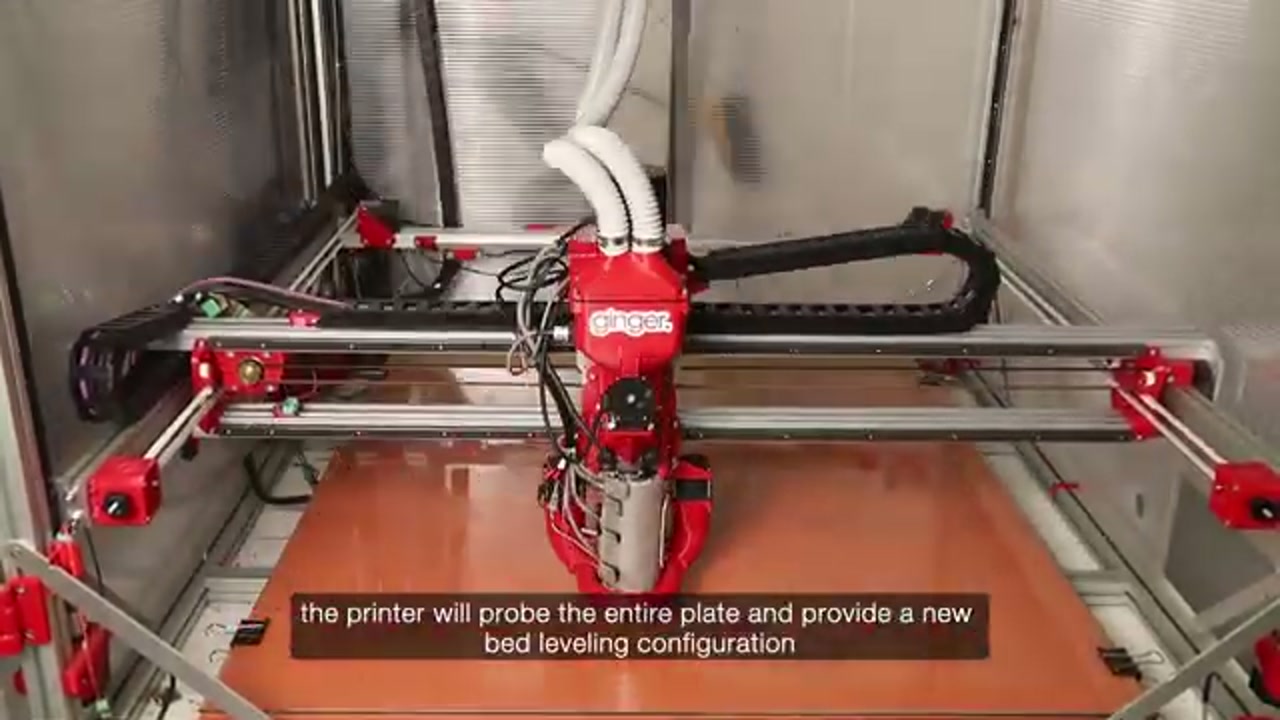
- Confirm the mesh map on screen looks consistent
- More → Save Config to store the result — the display asks to confirm and Klipper reboots when you accept. That restart is normal, not a fault
Z screw adjustment (manual tram)
Section titled “Z screw adjustment (manual tram)”Before running the full bed mesh, the Z lead screws should be trammed so all four corners are at the same height. This uses the screw_adjustment macro:
- Bed must be empty (no print, no objects)
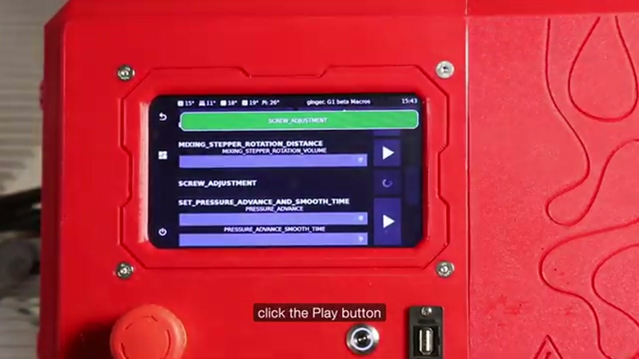
- From the display, run
SCREW_ADJUSTMENTfrom the Macros list (also reachable via More → Z Calibrate)
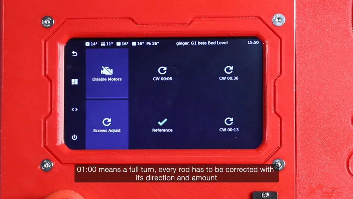
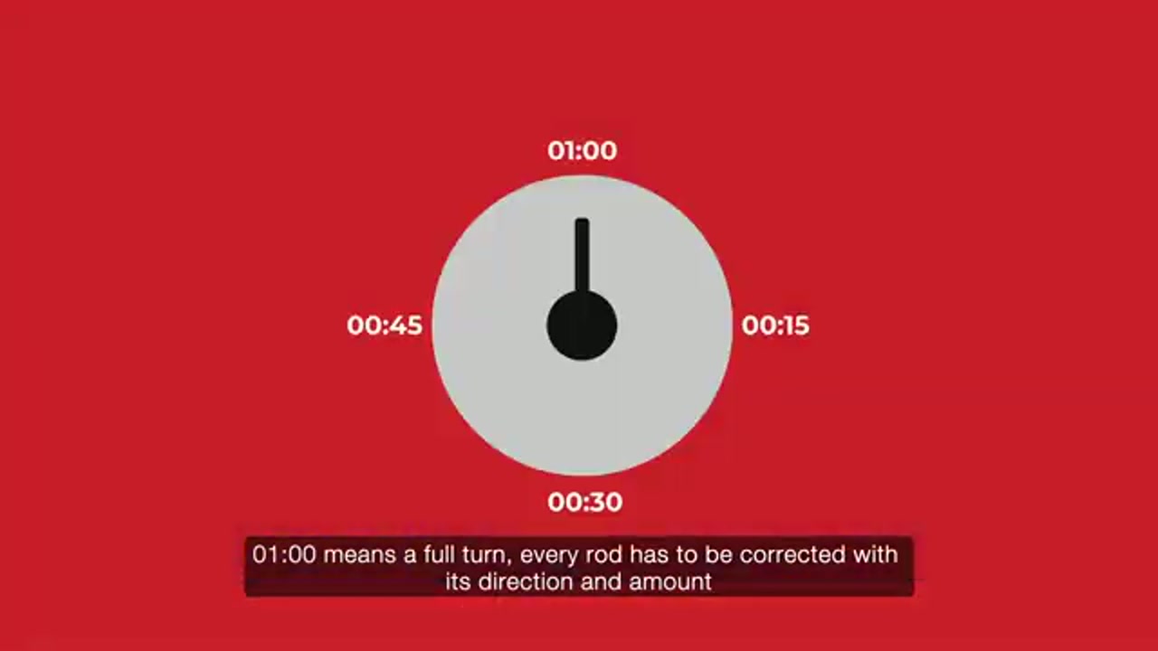
 3. The macro probes near each rod and reports each one as a direction and a clock reading —
 CW 00:36, CCW 00:13 and so on
-
The front-left corner is the reference — it is fixed, and it is the one shown already ticked. Turn the other three by the reported amount in the direction shown
-
Disable the motors first. There is a Disable Motors button on that same screen. The rods cannot be turned by hand while the steppers are holding them
-
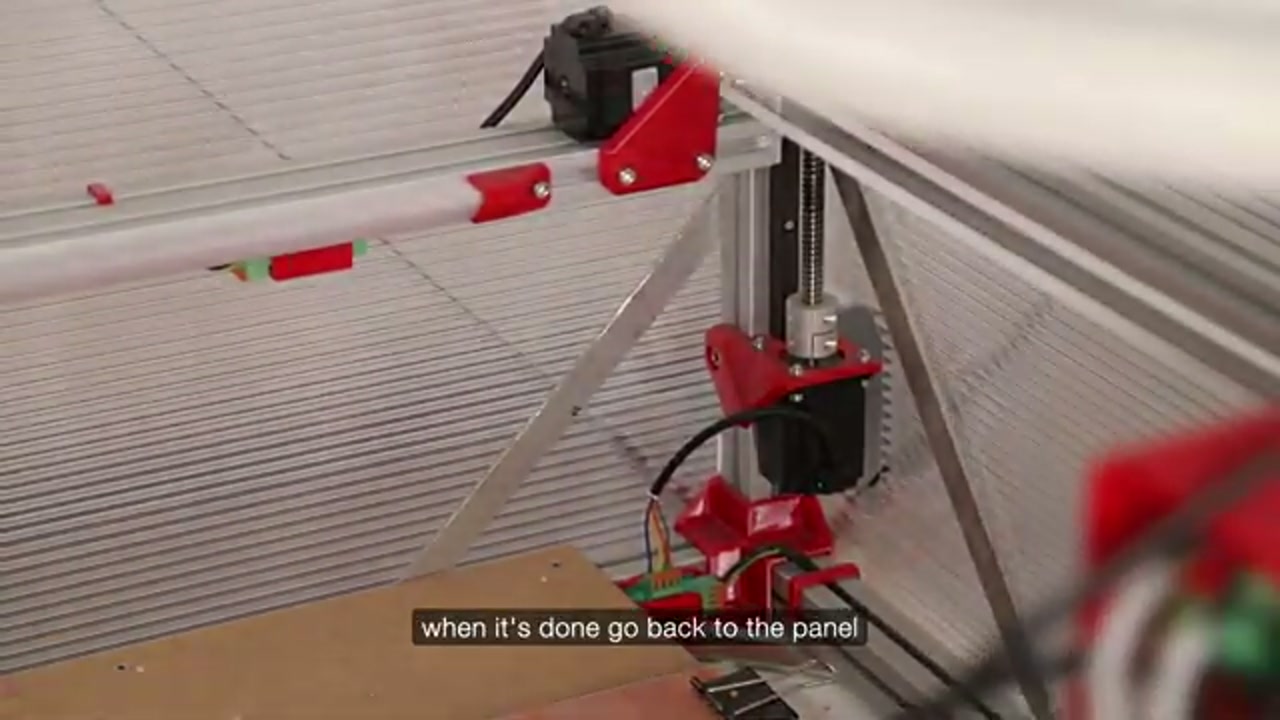
Turn the Z motor itself, by hand. Each one is reachable from outside the frame, so you do not have to work inside the machine to do it
- The display shows a clockwise/counter-clockwise diagram for each rod
- Re-run the macro until all four Z rods are ticked green — that is the finished state, not a number you have to interpret
- Save when it asks. The dialog warns Klipper will reboot; that is expected, click Accept
- Then run a full Bed Leveling mesh
The two meshes, and which one a print uses
Section titled “The two meshes, and which one a print uses”The machine keeps bed meshes under names, and there are two that matter.
global is the one BED_LEVEL produces: a full probe of the whole bed,
saved. LOAD_MESH loads it back without re-probing.
mesh1 is written fresh at the start of a print, probed only across the area
the part occupies rather than the whole bed.
Which of the two a print uses is decided by one parameter in the START_PRINT
line at the top of the G-code file:
START_PRINT carries | What happens |
|---|---|
KAMP_LEVELING=1 | Homes and probes fresh over the part, as mesh1 |
KAMP_LEVELING=0, or nothing | Homes and loads the stored global |
Ginger Slicer sends KAMP_LEVELING=1, so a print sliced normally probes for
itself every time and you never have to think about the stored mesh.
This is also why the Heightmap page can show a mesh you do not recognise: after
a normal print it is mesh1, the adaptive one, not the full-bed global.
When to re-level
Section titled “When to re-level”- After every nozzle change
- After moving the machine
- After replacing endstops / probe / cables
- Monthly during routine use
- If the first layer suddenly looks wrong
Known issues
Section titled “Known issues”- Z offset and first layer — the most common downstream problem
- Probe Z offset drifting after cable changes → re-tune live Z and save
- Mesh saved from display not loaded by slicer G-code → run from the correct source
- Bed leveling pushes nozzle hard into bed → probe Z offset diverged from nozzle
Probe arm bending / breaking
Section titled “Probe arm bending / breaking”Causes — the probe fails to descend or trigger, so the printer keeps lowering Z and crashes the extruder into the bed:
- Plastic stuck under the nozzle — the nozzle hits the glass before the probe can trigger (see Before homing or leveling)
- The servo did not actuate — the switch never came down, so there is no probe signal
- Bad 3-pin JST connector — the black 3-pin JST that connects the servo to the board behind the extruder may look fine but the internal metal pins are not making good contact. This is a very common cause and can also make the servo actuate during a print, dropping the probe so it hits the print or drags across the bed mid-job
How to identify:
- The extruder slams into the bed at the start of a leveling routine, or the probe suddenly drops during a print
- The probe arm is visibly bent after the event
- The probe/servo cable may have come loose
Fix:
- Re-seat and inspect the black 3-pin JST servo connector behind the extruder — reseat it even if it looks OK, since the metal pins often lose contact. This is the most common cause
- Confirm the servo actually lowers the switch during probing
- Replace the bent printed probe arm (E21) if needed — download the STL and reprint it. Do not remove the factory-calibrated metal arm that the printed part mounts to
- After repair, re-run bed leveling carefully and verify the probe triggers before the nozzle reaches the bed
- Set Z offset conservatively positive (nozzle higher) until you confirm the probe triggers reliably
Maintenance
Section titled “Maintenance”- Keep the probe clean (no pellet dust on the sensor face)
- Check probe cable routing — no sharp bends
- Verify the bed surface is flat (no warps, no debris) before leveling
Bed orientation reference
Section titled “Bed orientation reference”The bed has a “FRONT / ginger.” label on the front crossbar — use this to orient the probe arm correctly during assembly and after any mechanical maintenance.
Related notes
Section titled “Related notes”- Z offset and first layer
- Bed surface
- Bed heater
- Initial calibration
- Nozzle set