
Print checklist
The steps to follow, in order, for every print.
Most failed prints come down to one of two things:
- The plastic falls. The overhang is too steep for a layer that is too high.
- The layer has no time to cool. It is still soft when the nozzle comes back: the plastic coming out pushes on it, deforms it, and it collapses or the nozzle hits it.
Every drawing uses the same symbols:
1. Prepare the model in Ginger Slicer
Section titled “1. Prepare the model in Ginger Slicer”Before you start, switch Ginger Slicer to Advanced mode, bottom left, and keep it there: some of the settings below only show in Advanced mode.

1.1 Check the geometry
Section titled “1.1 Check the geometry”Import the model into Ginger Slicer and check three things: thickness, supports and bridges.
Thickness
Section titled “Thickness”Thickness here means how thick each part of the model is seen from above, within a layer — the width of a wall, a rib or a tab — not its height.
Every part of the model has to leave room for one line along each edge: at least 2× the nozzle diameter. Between 1.5× and 2× it still works: Arachne — the way Ginger Slicer builds the walls, already on in every default profile — narrows the lines to fit. Thinner than 1.5×, there is no room for a line along each edge.
Where the model is too thin, the slicer still tries to put material there — but there is no room for it. The two lines along the edges become one single line, and that is the problem: the wall is no longer one closed loop. The single line has a start and an end that are never stitched together, and the slicer has to stop and add a travel — the nozzle moving without printing — to reach the rest of the layer. In the worst cases it puts no line there at all and leaves a gap.
A single line is fine only when it closes on itself as a loop, as in vase mode.
You do not have to measure the model yourself: the preview shows it, see Check the thickness in the preview below.
Check the thickness in the preview
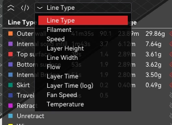
Section titled “Check the thickness in the preview”Turn on the Line Width view. After slicing, switch to Preview, open the dropdown at the top right and choose Line Width.
Read it. Every line is coloured by how wide it is, from blue (the narrowest) to red (the widest); the legend gives the width of each colour in millimetres. Red only means wide — it is not an error. The line width is a setting you choose in the process profile; in this example it is 1.9 mm, and those walls show blue-green.
Follow the walls through the thin parts of the model:
- the wall runs as one closed loop, with a line along each edge: the thickness is fine
- the lines along the edges change colour: Arachne is adjusting their width to the space — still fine
- there is no loop through the thin part, just one line — or no line at all: that part is too thin for this nozzle
A test part in Ginger Slicer, 1.8 mm nozzle, default profile, layer 11. The colours change where Arachne widens or narrows the lines; the problem starts where the two lines become one, and where there is no line left over the shaded model.
If a part is too thin, use a smaller nozzle — the sizes are listed in Nozzle set — or change the model so that part is thicker. Then slice and check again.
Supports: where they land
Section titled “Supports: where they land”Supports belong under shapes that stick out and are convex — rounded or pointed outwards, like the underside of a ball: there they touch the part over a small area only, and come off easily.
Not under large flat surfaces. With the 1.8 mm nozzle, a large flat surface resting on supports touches them everywhere, and it takes a lot of force to get it off.
If supports land under a large flat surface, reorient the model in Ginger Slicer — for example, turn it 45°. Left as it is, in some cases it wastes material and the part ends up thrown away. You can turn it on any axis: finding the best rotation for your part is up to you. Experienced users can also reorient it in CAD, with custom supports.
A part tipped onto a corner or an edge must not roll. In Ginger Slicer:
- Tip it with Rotate [R] around X or Y — turning it around Z only spins it on the bed
- Cut flat the corner that touches the bed, with Cut [C] or in CAD: a flat face 3–4 times the nozzle wide, so the part rests on a face instead of a point
- Add a brim
- In Process → Support, tick Enable support — without it, painted supports are not printed
- With Support Painting [L], paint a few supports either side of the corner — just enough to act like chocks under a car’s wheels
- Slice, and check in the Preview that the chocks are there
Bridges: no wider than 3–4 cm
Section titled “Bridges: no wider than 3–4 cm”A pellet layer is too heavy to span a gap: with the 1.8 mm nozzle, 3–4 cm at most. Measure the gap with Measure [U] in Ginger Slicer, or in CAD.
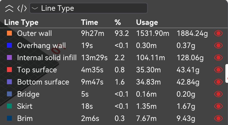
To find bridges, open the Preview in the Line Type view and open its legend with the double arrow at the left of the Line Type bar: Bridge is one of the lines.
Then move the layer slider, on the right, up to the top of each opening:
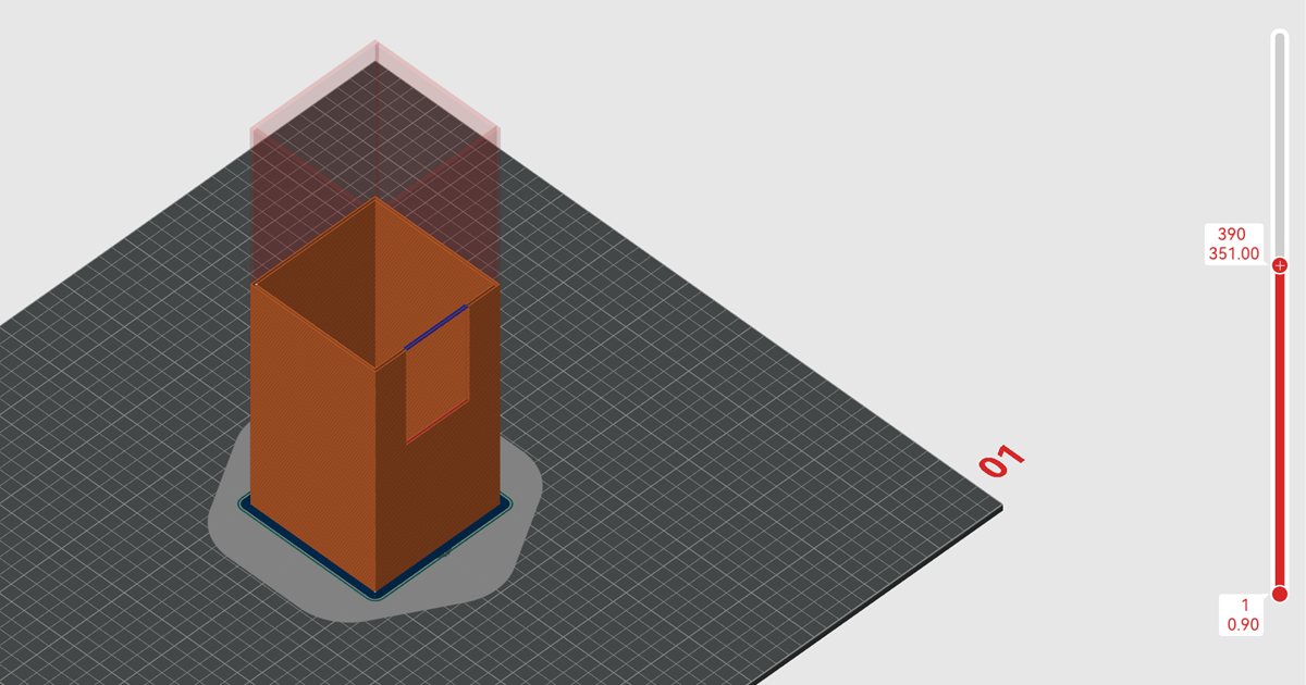
Wider than 3–4 cm: first reorient the part with Rotate [R]. The axis matters: this column tipped 45° around Y turns the window onto its corner and the bridge is gone; around X the top of the window stays level and the bridge comes back as Overhang wall — check both in the legend.
Tipped over, the part stands on an edge (see the corner steps above), and a tall one leans out past its base and can fall. With Support Painting [L], paint supports under the face it leans towards, from the bed up, one near each end. For them to reach the part, in Process → Support set Type to Normal (auto) and Support/object xy distance to 0.5 mm — at the default distance they never touch it.
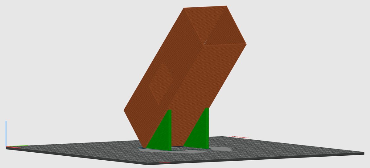
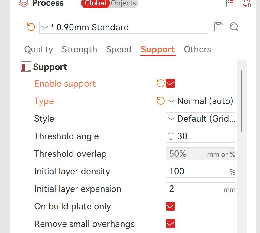
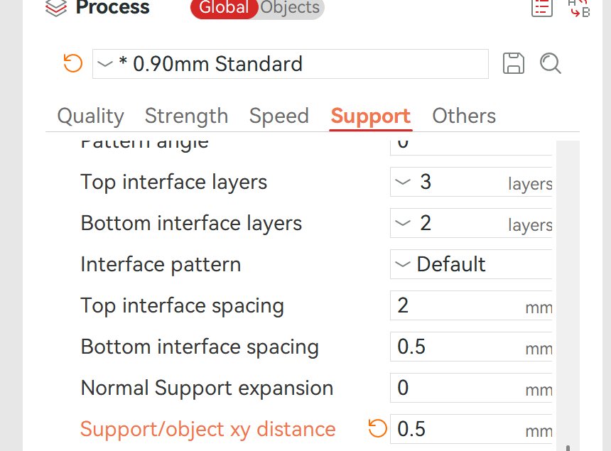
When no orientation gets rid of the bridge, support it. Ginger Slicer does not put supports there on its own: in Process → Support, tick Enable support and untick both Support critical regions only and Remove small overhangs, then slice again.
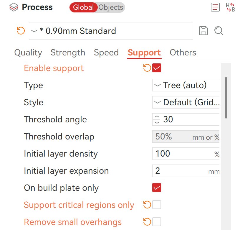
The layer resting on the supports is still listed as Bridge: what matters is that the supports reach it.
1.2 Choose the nozzle
Section titled “1.2 Choose the nozzle”In Ginger Slicer the nozzle is chosen in the Printer list: there is one printer profile per nozzle.
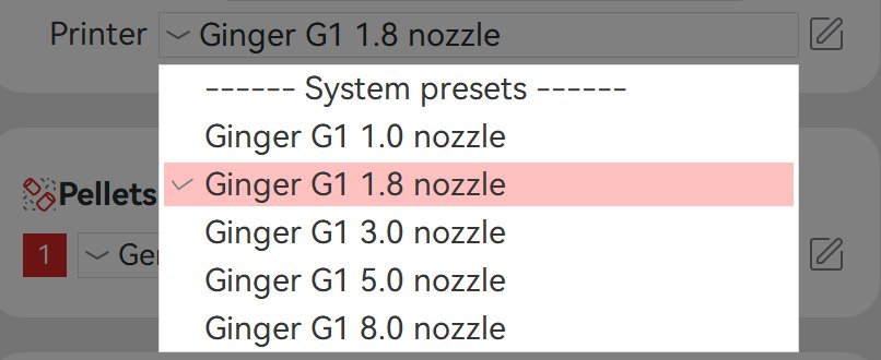
- 1.8 mm — complex parts that need supports.
- 3 mm — the other most-used nozzle. Supports work but are hard to remove, so design the part to need none, and watch the overhangs. Inside, use Lightning infill (step 1.7): the part stays hollow and weighs less.
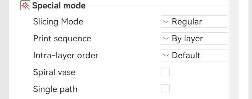
- 5 and 8 mm — mostly Spiral vase (Process → Others → Special mode), with the geometry designed for it.
1.3 Layer height and line width
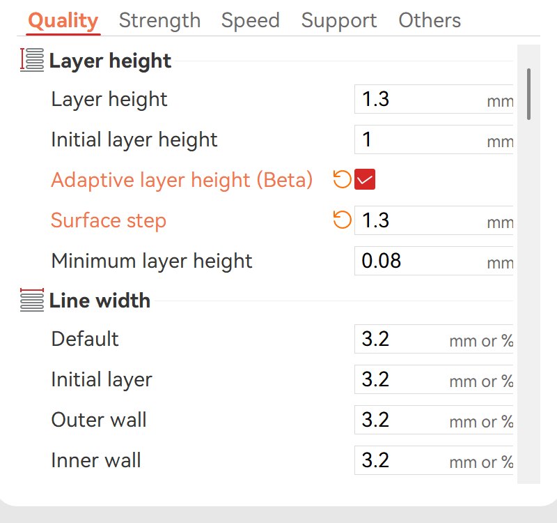
Section titled “1.3 Layer height and line width”Process → Quality → Layer height and Line width. The line width is how thick the wall is.
A layer that is too high over an overhang is what makes the plastic fall.
1.4 Adaptive layer height
Section titled “1.4 Adaptive layer height”Process → Quality → Layer height → Adaptive layer height (Beta). Ginger Slicer makes the layers thinner where the overhang gets steeper.
- Surface step: the layer height again, measured along the normal to the surface instead of along Z. Set it to the same value as Layer height.
- Minimum layer height: leave it as it is.
1.5 Make overhangs printable
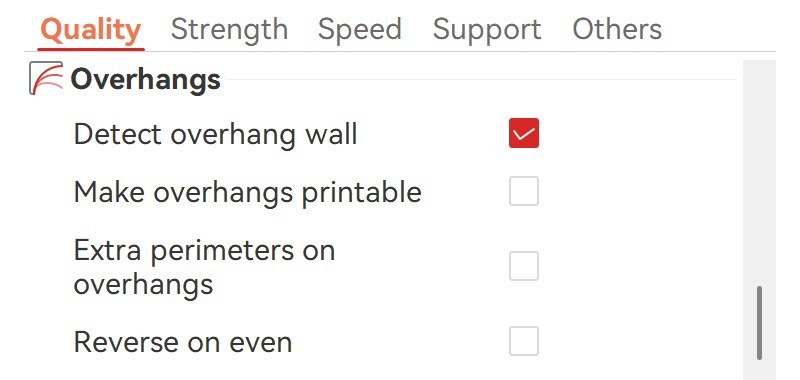
Section titled “1.5 Make overhangs printable”Process → Quality → Overhangs → Make overhangs printable. It changes the geometry of the model so the overhangs print without supports: use it only where the part can change a little.
1.6 Walls
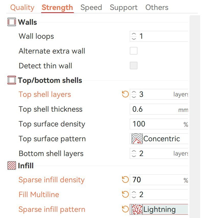
Section titled “1.6 Walls”Process → Strength → Walls → Wall loops. Usually 1 is enough.
1.7 Infill and top
Section titled “1.7 Infill and top”Process → Strength → Infill: Sparse infill pattern Lightning, Sparse infill density 70%, Fill Multiline 2.
Lightning holds up the top of the part, which otherwise has nothing under it to close on. Give the top at least 3 layers: Process → Strength → Top/bottom shells → Top shell layers.
1.8 Bottom
Section titled “1.8 Bottom”Same group, Bottom shell layers: usually 2–3.
1.9 Brim
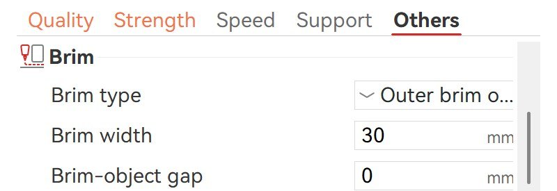
Section titled “1.9 Brim”Process → Others → Brim: Brim type and Brim width. A brim is usually used.
On long, narrow, tall parts, where warping pulls the hardest — a thin wall, like a tray bending in the oven — make it 30 mm wide.
The brim is printed at the Initial layer height (Process → Quality → Layer height). Leave it as the profile sets it.
1.10 Cooling
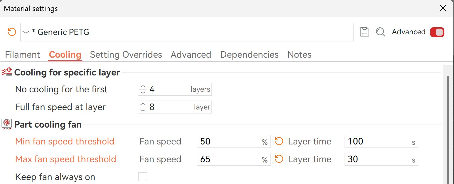
Section titled “1.10 Cooling”Open the Pellets profile with the pencil next to it, then Cooling → Part cooling fan:
- Layer time: how long each layer must take to cool, depending on nozzle and material — see Material profiles
- Fan speed: 65% at most (Max fan speed threshold), 50% at least (Min fan speed threshold). The fans start at 50%; at 70% they are already very strong
1.11 Check layer time and layer height in the preview
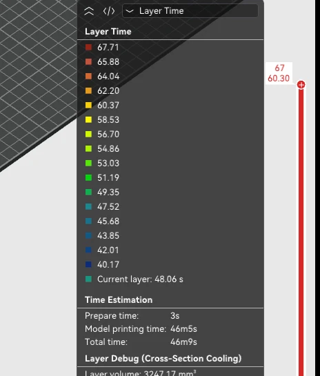
Section titled “1.11 Check layer time and layer height in the preview”Slice, and in the Preview switch to the Layer Time and Layer Height views — see Reading Layer Time.
2. Before printing
Section titled “2. Before printing”- The material matches the profile. The Pellets profile in Ginger Slicer names the brand and the grade: they must be those of the pellets in the hopper, and the profile must be tested for them. If your material is not in the list, start from the profile of a similar material or from a Generic one — see Creating a material profile
- Lubricant, if the material needs it — see SmoothFlow
- The material is dry. Bubbles in the extruded plastic mean moisture — see Starting the dryer and PETG foaming and moisture
- No old or different material in the feeding system, or it contaminates the new one — see Material change and purge and Hopper cleaning
- The bed is clean, and nothing is in the way of the bed leveling — see Bed leveling system
- The right product is on the bed, so the glass does not break — for example DimaFix with PETG. See Bed adhesion sprays
- The printer is connected and ready — see Connecting Ginger Slicer to the G1
3. Start the print
Section titled “3. Start the print”- Upload and print from Ginger Slicer — see Running a print
- Watch the homing. The bed leveling probe must touch the bed, and the nozzle must not hit it first with solid plastic left on its tip
- Check the first layer. It must come out at the height set in Ginger Slicer; if it does not, adjust the Z offset — see Z offset and first layer