
The Ginger Slicer window
Ginger Slicer is built on OrcaSlicer, so most of it will look familiar if you have used one. What follows is the part you need before your first print, and the handful of places where this one differs.
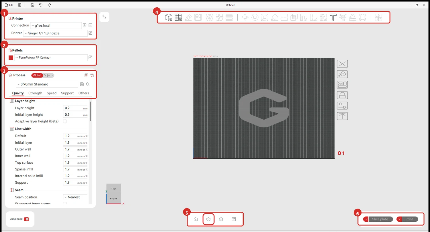
The three panels down the left
Section titled “The three panels down the left”They are stacked in the order the decisions happen, and between them they determine almost everything about a print.
1 · Printer. Which machine, and which nozzle — the profiles are named Ginger G1 1.8 nozzle and so on, one per nozzle in the set. Changing nozzle means changing profile here, not just changing the hardware. Connection is the printer’s address, the same g1os.local you open in a browser.
2 · Pellets. The material.
3 · Process. Named for its layer height — 0.90mm Standard means 0.9 mm layers. Everything below is grouped into five tabs:
| Tab | What lives there |
|---|---|
| Quality | Layer height, line widths, seam position |
| Strength | Walls, top and bottom shells, infill |
| Speed | Feed rates per feature |
| Support | Supports and rafts |
| Others | Skirt, brim, special modes |
The rest of the window
Section titled “The rest of the window”4 · The toolbar acts on the model on the plate: move, rotate, scale, cut, and so on. It does nothing until something is loaded.
5 · Prepare and Preview. The left icon is the plate as you arrange it; the next is the sliced result, layer by layer, which is where you check what the machine will actually do before sending it.
6 · Slice plate, then Print. Slice first — Print stays greyed until there is something sliced to send.
Advanced, bottom left, reveals the settings that are hidden by default. Most of what this wiki refers to is visible without it.
What the Strength tab controls
Section titled “What the Strength tab controls”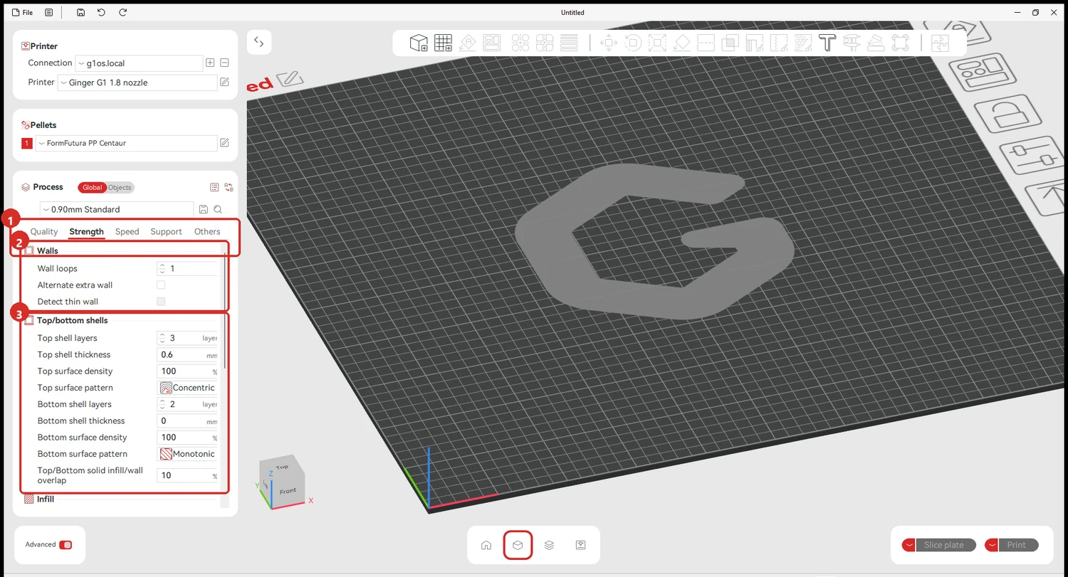
1 selects the tab. 2 is the wall count — how many perimeters the outside gets. 3 is the top and bottom shells, and the one worth knowing on this machine is Bottom shell layers: the shipped process uses 2, and going much above that traps heat in the first layers of a small part. See PLA.
The workflow, in order
Section titled “The workflow, in order”This is how a print is actually set up. The order matters: each choice narrows the ones after it.
-
Import the model. File → Import, or drag it onto the plate
-
Choose the nozzle in Printer. Not the one you wish you had fitted — the one that is on the machine. Everything downstream is sized around it
-
Choose the material in Pellets, matching the pellets in the hopper. See Material profiles
-
Set up the process. This is where the work is: walls, infill, and the rest of what the part needs
-
Slice, then check the result before printing — see below
-
Save the 3MF. This is the step people skip, and it is the one that matters most later
Checking the slice before you print
Section titled “Checking the slice before you print”Slicing produces a plan. Looking at that plan is what catches a problem while it is still free to fix.
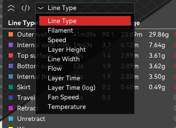
Switch to Preview and use the dropdown at the top right to re-colour the model by whatever you want to inspect.
| View | What it tells you |
|---|---|
| Layer Time | How long each layer takes. Look at this one first |
| Fan Speed | Where cooling is on, and how hard |
| Travel — shown under Line Type | The moves that extrude nothing. A lot of travel is a lot of chances to string |
| Layer Height | Useful when the height is not constant |
| Line Width, Flow, Speed | The same picture from the flow side |
| Line Type | Wall, infill, skirt, brim — the default, and the one with the time and weight breakdown |
Reading Layer Time
Section titled “Reading Layer Time”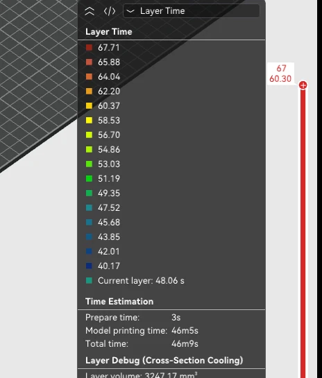
The scale is seconds per layer, red at the top for the slowest layers and blue at the bottom for the fastest. The blue end is the one to worry about: a layer laid down faster than it can cool is where quality goes, whatever the flow figures say. See Max Volumetric Speed, where layer time is named as the real bottleneck.
Below the scale the panel gives the estimate for the whole job, and a Layer Debug (Cross-Section Cooling) block with the volume, path length and average bead cross-section of the layer you are looking at.
Save the 3MF
Section titled “Save the 3MF”The 3MF is the project file. It stores the model, the plate arrangement, and every setting that produced this slice — printer, material, process and any change you made to them.
That makes it the only thing worth keeping. A G-code file records what the machine should do; the 3MF records why, and lets you reopen the job months later, change one thing and re-slice it.
Save it whenever a job is worth repeating, and save it before you start experimenting.
Related notes
Section titled “Related notes”- Material profiles — every profile that ships, with its temperatures
- Connecting Ginger Slicer to the G1
- FGF-specific settings
- Rotation Volume calibration
- Nozzle set — which nozzle for which job