
Extruder screw
The extruder screw (auger) is the core component of the G1 pellet extruder. It sits inside the barrel, driven by the Main extruder motor, and compresses pellets from the hopper downward through the three Multi-Heating Zones to the nozzle.
Function
Section titled “Function”- Pellets fall from the hopper into the top of the barrel
- The rotating screw grips and compresses the pellets
- As pellets travel down through the heating zones, they melt progressively
- Molten material is pushed through the nozzle at controlled pressure
The screw has a 2:1 compression ratio between the feeding end and the nozzle end.
New machine — first use
Section titled “New machine — first use”New machines may have machining oil residue and machining debris on the screw from manufacturing, which can end up in the material during the first extrusions. This is normal:
- The first extrusions may appear slightly discolored or smell different
- Purge with the first material at normal printing temperature until output is clean and consistent
- No special action needed beyond this initial purge
Signs of screw / barrel problems
Section titled “Signs of screw / barrel problems”| Symptom | Likely cause |
|---|---|
| Dark or black particles in extrusion | Degraded or burnt material stuck in barrel |
| Material melted at screw entrance (visible from top) | Feeding Zone (T0) too hot, or printing at low flow rate |
| Motor clicks / skips steps | Material too viscous, clog forming, or temperature wrong |
| Output suddenly becomes more fluid then drops | Backpressure fluctuation from partial clog |
Clearing a clog at the screw entrance (feeding zone)
Section titled “Clearing a clog at the screw entrance (feeding zone)”This is the most common extruder problem. The machine suddenly stops extruding material and the cause isn’t obvious. Opening the hopper (piece E04, the one with the two black knobs) reveals a piece of fused plastic at the entrance of the screw.
- Make sure the extruder is stopped (not rotating)
- Open the hopper (E04 — loosen the two black knobs)
- Remove the fused plastic with a long screwdriver or pliers — it comes out easily
- Close the hopper and resume printing
- To prevent recurrence, lower the Feeding Zone temperature (T0) by 10–20°C
Why it happens: when printing at a low flow rate (e.g. 50–100 mm³/s), the plastic travels slowly through the extruder and can stick to the screw, forming the plug at the screw entrance.
Deep cleaning (barrel flush)
Section titled “Deep cleaning (barrel flush)”For stubborn contamination (black specks in output, degraded material smell):
- Set the zone temperatures according to the material being purged out — there is no single figure, it depends on what is currently in the barrel
- Purge at high flow rate (250+ mm³/s) to mechanically push out contaminated material
- If needed, run something through the barrel to scrub it — see below
What to purge with
Section titled “What to purge with”| What it is | Temperature | |
|---|---|---|
| Injection-grade PP | The cheap option: a commodity polypropylene of the kind used for injection moulding. Flows easily and pushes the old material out mechanically | Its own, low |
| Dyna-Purge F | Purpose-made, non-abrasive, for extrusion and injection | 160–302°C — covers PLA and PETG |
| Airtech Dahlpram SP209 | Purpose-made, non-abrasive, designed for pellet-fed additive machines | Dahlpram range published as 254–410°C |
Technical specifications
Section titled “Technical specifications”| Parameter | Value |
|---|---|
| Screw compression ratio | 2:1 |
| Extruder assembly weight | 11 kg |
| Drive | NEMA 34 stepper + 5:1 gearbox, screw coupled to the gearbox output |
| Motor driver | DM860T (see Main extruder motor) |
| Operating voltage | 55V via step-up converter |
The weight is relevant for robotic arm integration or remote head mounting setups.
Removing the screw for deep cleaning
Section titled “Removing the screw for deep cleaning”The motor, gearbox and screw form a single body — the screw is held to the gearbox by a coupler. To pull the screw you extract that whole assembly upward. The extruder itself stays mounted on the carriage.
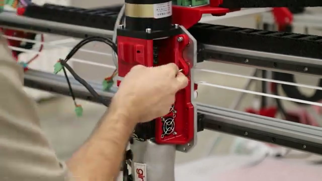
- Bring the extruder up to printing temperature and keep it hot — the screw will not come out of the barrel cold
- Remove the 4 vertical screws connecting the gearbox to the 3D-printed part E01
- Lift the motor + gearbox + screw assembly out through the top, turning it by hand as you pull to walk the screw out of the barrel
- Clean the screw and the barrel bore
- Reassemble in reverse order
Preventing screw clogging
Section titled “Preventing screw clogging”- Keep Feeding Zone (T0) at the recommended temperature for the material — too hot causes pellets to melt before they enter the compression zone, forming plugs
- Use SmoothFlow — it stops PETG from sticking to the steel of the screw in the Feeding Zone. Without it the material cakes onto the screw and the stepper starts losing steps
- Do not leave the machine at printing temperature for extended periods without extruding — material degrades and can burn onto the screw