
Hopper
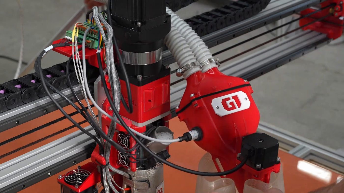
The pellet container mounted directly above the extruder. Pellets enter from the corrugated tube (vacuum-fed) and are pushed into the inlet of the extrusion screw by an auger running inside the hopper.
Function
Section titled “Function”- Buffers pellets between the material source and the extruder
- Maintains a steady supply during printing
- Carries the capacitive level probe that drives the vacuum cycle
- Houses the auger and the E1 mixing stepper that push material into the extrusion screw
Location
Section titled “Location”Top of the extruder assembly. The corrugated tubes enter from the top through a sealed clamp + gasket joint.
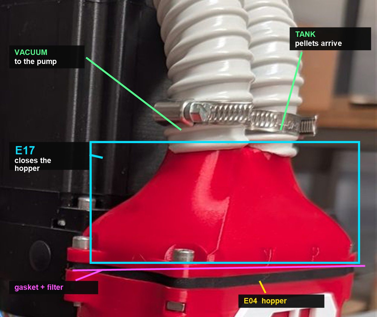
The two tubes on E17
Section titled “The two tubes on E17”E17 carries two identical corrugated tubes, each held by a hose clamp. They look the same — only their position and routing tell them apart:
| Tube | Port | Function |
|---|---|---|
| Right (viewed as in the photo below) | TANK | Where pellets arrive. It can be connected to any material container — it does not have to be the supplied bucket |
| Left | VACUUM | Runs to the vacuum pump |
Between E17 and E04 sits a filter. It is what stops the pellets from being drawn straight up the vacuum line: air passes, pellets stay in the hopper. Without it the vacuum simply swallows the material.
Components
Section titled “Components”| Part | Purpose |
|---|---|
| Hopper body | Container holding ~500 g of pellets |
| E17 | The red cap that closes the hopper and carries the two tube connections |
| Gasket | Air seal at the E17 joint. It is directional — fitted the wrong way round it lets air bypass and suction fails |
| Filter | Sits with the gasket between E17 and E04, keeping pellets out of the vacuum line |
| Clamp | Holds each tube firmly on its E17 stub |
| Level probe | Capacitive probe that drives the vacuum cycle — see Level probe and feeding cycle |
| Auger (coclea) | Screw inside the hopper that pushes pellets into the inlet of the extrusion screw |
| Mixing stepper (E1) | Hanpose 57HS41 driving the auger, mounted on the flank of the hopper at 45° to match the material inlet — see Main extruder motor |
| Feed throat | Bottom outlet feeding the screw |
Specifications
Section titled “Specifications”- Capacity: ~500 g, depending on the density and shape of the granule
- Sealed against air (required for vacuum to work)
- Gasket: replaceable when worn
Level probe and the feeding cycle
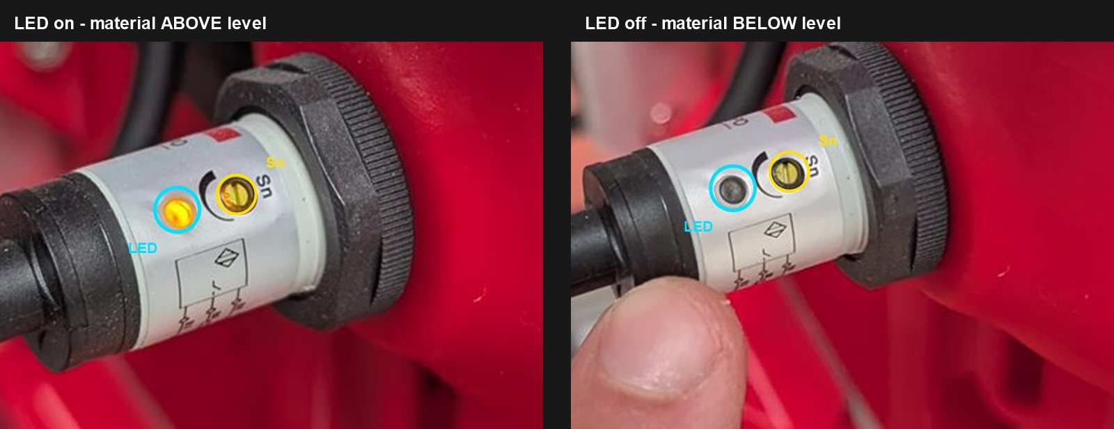
Section titled “Level probe and the feeding cycle”Feeding is driven by a capacitive proximity probe — a threaded cylindrical sensor screwed into the side wall of the hopper and locked with a ring nut. It senses the pellets through the wall; nothing protrudes into the pellet path.
You can read the state from outside the machine, without opening anything — the probe has a single indicator LED on its body:
| LED | Probe state | Meaning |
|---|---|---|
| On (orange) | On | Material is above level |
| Off (grey) | Off | Material is below level |
What happens, in short
Section titled “What happens, in short”With FEEDER on and the probe reading off:
- The vacuum runs for about 3 seconds
- Then 5 seconds of silence while the probe is re-checked
- If material still has not arrived, it tries again — four rounds in total
- Still nothing after roughly 27 seconds? The buzzer sounds: 3 seconds on, 17 seconds off, repeating
So a few rounds of suction in a row are normal with heavy or slow-moving material. What is not normal is reaching the buzzer.
Normal cadence is one feeding event every 10–20 minutes, depending on the print’s flow rate. Much more frequent cycling points to a suction leak — see Hopper suction problems.
The buzzer
Section titled “The buzzer”The buzzer means the hopper is not filling: the system has tried four rounds of suction and the probe never switched on.
Three usual causes, in order:
- A blocked tube
- The vacuum cleaner is off — suspect this if you never hear it start
- The probe connector has come loose
In detail — the auto feeding firmware
Section titled “In detail — the auto feeding firmware”Exact timings, pins and why a flickering LED breaks feeding
Auto feeding is not handled by Klipper. It runs on its own board in the panel box — Ginger.Feeding, carrying an Arduino Nano — with its own firmware, an open-source sketch: G1-AutoFeeding.
That board has no USB connection to the Raspberry Pi. It takes the FEEDER signal from the extruder board over a short link and decides for itself when to run the vacuum, which is why the cycle carries on regardless of what Klipper is doing. Nothing in Mainsail can see it or update it — see Flashing the control boards.
Inputs and outputs
| Pin | Function |
|---|---|
| 2 | Vacuum relay |
| 3 | Status LED on the board — not the probe’s own LED |
| 4 | Level probe |
| 9 | FEEDER enable |
| 12 | Buzzer |
The rule. The vacuum is switched off whenever FEEDER is off or the probe reads high. Probe high therefore means material present — the same thing the probe’s LED shows.
The timings
| Setting | Value |
|---|---|
| Suction burst | 1 s, repeated 3× back to back → ~3 s of suction |
| Silent pause between rounds | 5 s |
| Rounds before the alarm | 4 |
| Buzzer | 3 s on, 17 s off, repeating |
| Delay after power-on before feeding is active | 10 s |
That gives roughly 27 seconds from the first attempt to the first beep, and a beep about every 47 seconds after that until the problem is fixed.
Why a flickering probe LED matters. Both the probe and the FEEDER input are debounced over 1 second across 10 consecutive samples — a state change is only accepted if all ten agree. A probe whose LED flickers never produces ten consistent readings, so the firmware never registers “material present” and keeps calling for more material even with a full hopper. This is the mechanism behind the sensitivity symptom described below.
Configurability. The timings are constants at the top of the sketch, so they can be changed for an unusually difficult material. This is not a customer-side adjustment — contact Ginger Additive support.
Sensitivity (Sn)
Section titled “Sensitivity (Sn)”Next to the LED there is a slotted screw marked Sn — the sensitivity trimmer. It is set in production and should not be touched.
The one case that justifies re-calibrating it is a material of unusually low density, such as a compound heavily loaded with natural fibres. The probe may then fail to see the pellets even with a full hopper.
The symptom is specific: with the hopper full, the LED flickers instead of staying steadily on. A flickering reading never survives the firmware’s debounce, so the machine keeps feeding a hopper that is already full. A steady LED means the sensitivity is fine — do not adjust it because feeding misbehaves for some other reason.
Moisture
Section titled “Moisture”The hopper is not insulated. Pellets coming out of the dryer cool to room temperature in it, and from that moment they start reabsorbing moisture from the air.
There is nothing to do about it at the hopper: it is not a sealing or insulation problem, and an open hopper is no worse than a closed one. Manage moisture upstream instead — dry the material properly and keep the hopper stocked with what you are about to print rather than filling it hours ahead. See PETG foaming and moisture and Dryer.
Maintenance
Section titled “Maintenance”The hopper is not a scheduled-maintenance item. There is nothing to service at fixed intervals — you open it when something happens, not on a calendar.
The one real case is cross-contamination: if you change material and notice the new one is contaminated with the previous one, clean the hopper out.
Cleaning the auger
Section titled “Cleaning the auger”Only needed if you run powder or liquid masterbatch — otherwise the auger does not need cleaning.
- Undo the 4 screws holding the E1 stepper to the hopper (E04)
- The auger comes out easily, still attached to the motor
- Clean it and reassemble
Assembly — mounting the hopper (step 2.2)
Section titled “Assembly — mounting the hopper (step 2.2)”The hopper is placed on the extruder inlet (step 2.2.1) and secured with 2 black knobs K01 (Knob M5) (step 2.2.2). 1 operator, 5 min.
Taking the hopper off to empty it
Section titled “Taking the hopper off to empty it”Those two knobs are also how you get the hopper off in normal use — to empty leftover material before a material change, for instance.
- Undo both knobs — both come off, the hopper is not hinged on one
- Lift the hopper away. The corrugated tube can stay connected while you handle it
- Tip the remaining pellets into a container
- Refit and do both knobs back up
From How the G1 Automatic Feeding System works — 3:33
See Material change and purge.
Feeding setup — critical reminders (from assembly manual step 5.2)
Section titled “Feeding setup — critical reminders (from assembly manual step 5.2)”The feeding circuit (step 5.2 of assembly manual) — 2 operators, 15 min:
- Screw the tube outlets onto the hopper (V08 M5x25 CIL, x4)
- Accommodate the tubes and secure with clamps (11.1)
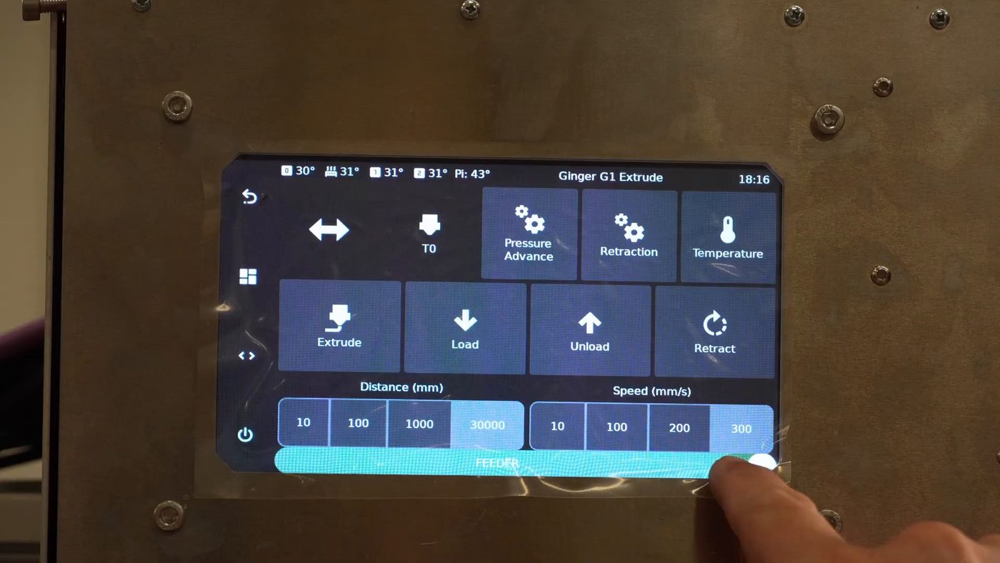
- Insert tubes into VACUUM and TANK ports — the auto-feeding activates automatically when launching a print, or can be manually activated via the FEEDER toggle in the “Extrude” menu
- Two flexi pipes (07.1 x2) connect the vacuum pump and pellet tank
From How the G1 Automatic Feeding System works — 3:18
Known issues
Section titled “Known issues”- Hopper suction problems — the #1 customer issue, often a gasket or clamp problem
- Crunching sound from non-uniform pellets — usually normal, see suction note
- Melt creeping up from the feed throat — feeding zone too hot, see Multi-Heating Zones
Versions
Section titled “Versions”The hopper was redesigned in April 2026 to fix suction problems, improving how it handles recycled and irregular pellets. Customers with recurring suction issues can request the new design from Ginger Additive.
Accessories
Section titled “Accessories”- Hopper extender — optional 3D-printed accessory for manual pellet refill from above. Useful when diagnosing the vacuum or doing frequent material changes. STL file available on request.