
Nozzle replacement
Replacing the nozzle on the G1 is a guided procedure triggered directly from the printer display. The built-in CHANGE_NOZZLE macro walks you through each step, positions the printhead automatically, and ensures the barrel is at the correct temperature before you touch anything.
Tools needed
Section titled “Tools needed”- Nozzle wrench (included in the G1 tool kit, bag 05.2) — fits the nozzle hex. The kit also ships 3 nozzles and 2 teflon tapes (bag 05.1)
- Second wrench — to counter-hold during final tightening
- A soft mallet, for a nozzle that will not start moving
- PTFE tape (teflon tape) — wrap 3 turns around the thread of the new nozzle before installation
- Heat-resistant gloves or a tissue — the barrel stays hot during the procedure
When to replace the nozzle
Section titled “When to replace the nozzle”There is no service interval — you replace it on symptoms, not on a schedule:
- Inconsistent line width even after Rotation Volume calibration
- Visible scoring, denting, or wear at the nozzle tip
- Switching to a different nozzle diameter
- After a crash that may have deformed the nozzle tip
Procedure
Section titled “Procedure”Step 1 — Start the CHANGE_NOZZLE macro
Section titled “Step 1 — Start the CHANGE_NOZZLE macro”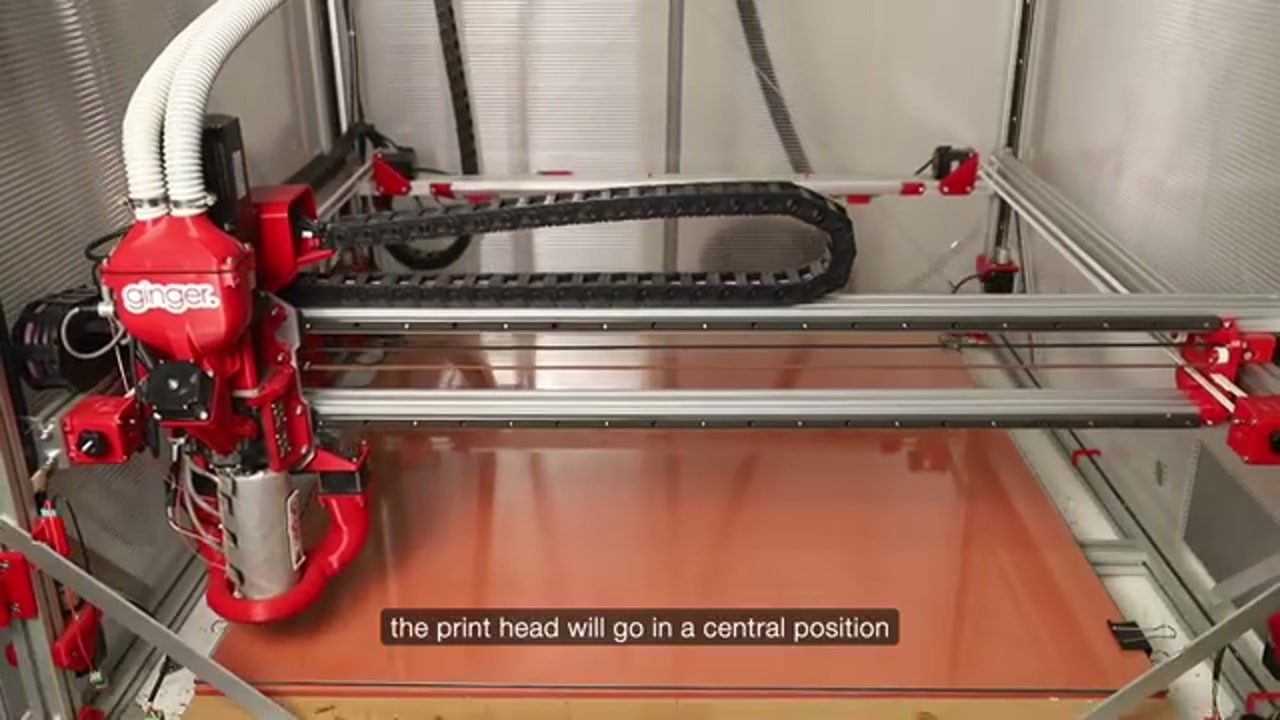
From the display, open More → Macros and run CHANGE_NOZZLE. The display then walks you through a 5-step guided procedure.
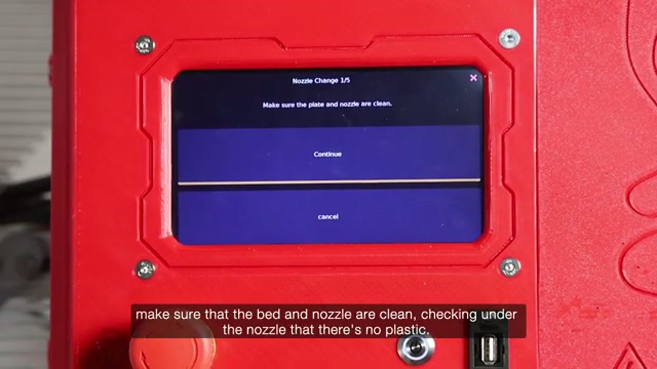
The display shows: “Make sure the plate and nozzle are clean”.
The printhead moves automatically to the centre of X with Y at 0 — the front of the bed, where the nozzle is within easy reach. The video calls this “a central position”, which undersells it: it comes to the front deliberately so you are not leaning over the bed.
Step 2 — Remove the protective ring
Section titled “Step 2 — Remove the protective ring”Remove the ring (protective collar) from around the printhead to expose the barrel and nozzle.
Step 3 — Open the heat cover
Section titled “Step 3 — Open the heat cover”The barrel is wrapped in an insulating cover held by clips. Open it to reach the nozzle — step 7 closes it again, and a print with it left open will not hold its zone temperatures.
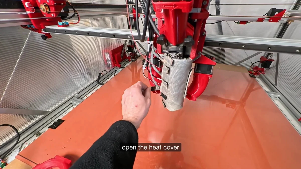
From G1 Nozzle Change — Quick Guide — 0:25, “open the heat cover”
Step 4 — Remove the old nozzle
Section titled “Step 4 — Remove the old nozzle”Unscrew the old nozzle with the gold wrench.
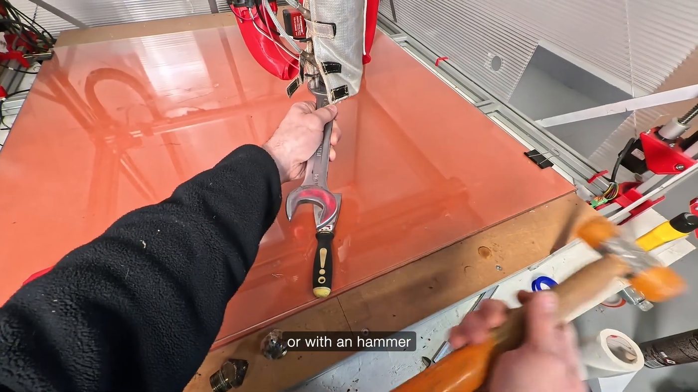
From G1 Nozzle Change — Quick Guide — 0:37
Remove all old PTFE tape from the threads of the old nozzle (discard it — do not reuse).
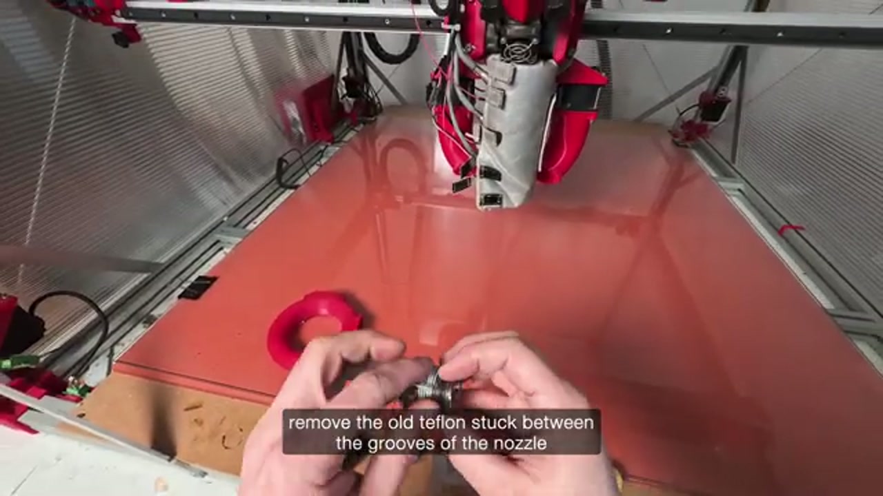
Step 5 — Prepare the new nozzle with PTFE tape
Section titled “Step 5 — Prepare the new nozzle with PTFE tape”Before installing the new nozzle, wrap PTFE tape (teflon tape) for exactly 3 turns around the thread. This seals the thread and prevents molten plastic from leaking along the barrel threads.
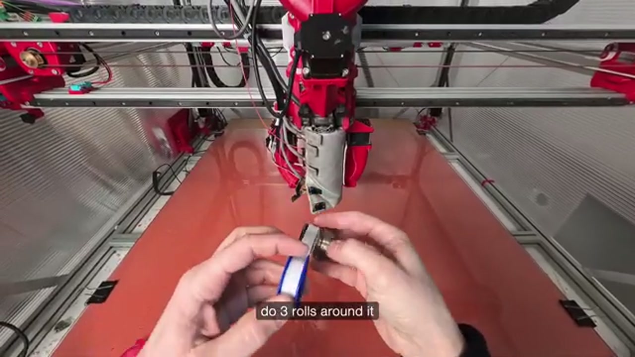
Step 6 — Install the new nozzle
Section titled “Step 6 — Install the new nozzle”Screw the new nozzle into the barrel by hand (finger-tight) — counter-clockwise as you look down at it, the opposite of the way you took the old one off. The barrel is still hot; work carefully.
Place two wrenches on the nozzle and wait for the barrel to reach full printing temperature before tightening.
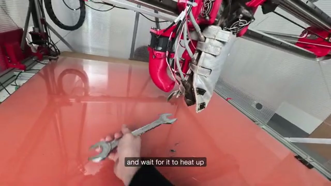
Step 7 — Tighten it hot, then close the cover
Section titled “Step 7 — Tighten it hot, then close the cover”Final tightening happens at temperature, and there is a step in the middle that is easy to skip:
- Screw it on until it seats, then back it off very slightly
- Let the barrel come up to temperature
- Once it is hot, tighten it firmly
The metal grows as it heats. Tightening cold and leaving it is what lets plastic weep along the thread later, and going straight to full torque cold is what strips it.
Use two wrenches: one to counter-hold the barrel, the other to apply the torque. Firm, not forced.
Then close the heat cover back around the barrel — the same one opened at step 3.
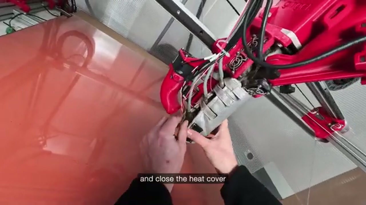
Step 8 — Completed
Section titled “Step 8 — Completed”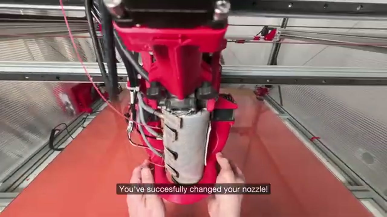
The nozzle is installed. Follow the prompts on the display to complete the remaining steps of the guided procedure.
After replacement
Section titled “After replacement”After any nozzle change:
- Recalibrate Z offset — the nozzle tip position changes with every nozzle swap. See Z offset and first layer.
- Run bed leveling — run the
BED_LEVELmacro from the display to generate a fresh mesh. See Bed leveling system. - Check Rotation Volume if switching to a different nozzle diameter — the flow characteristics change. See Rotation Volume calibration.
Related notes
Section titled “Related notes”- Nozzle set — available sizes, materials, layer height rules
- Z offset and first layer — recalibrate after every nozzle change
- Bed leveling system — re-level after nozzle change
- Nozzle and barrel clog — if the nozzle is blocked
- Barrel clog purging procedure — full purge when severely blocked
- Rotation Volume calibration — recalibrate flow after diameter change
Sources
Section titled “Sources”- G1 Nozzle Change — Quick Guide — Ginger Additive, 1:52. The short reference version: remove the ring, open the heat cover, free a seized nozzle, PTFE tape, refit.