
Panel Box wiring
The Panel Box is the main electronics enclosure of the G1, at the front of the machine around the display. It houses the Raspberry Pi and the extruder_board (the green PCB — see Klipper MCU extruder_board).
Overview — the 14 wires
Section titled “Overview — the 14 wires”During assembly, 14 wires (WIRE 1 through WIRE 14) connect the Panel Box to the printer hardware. There are only 14 — one of them, WIRE 1, is the main POWER cable. The 24V PSU is housed in the power box (see Power supply 24V), not as extra panel-box wires.
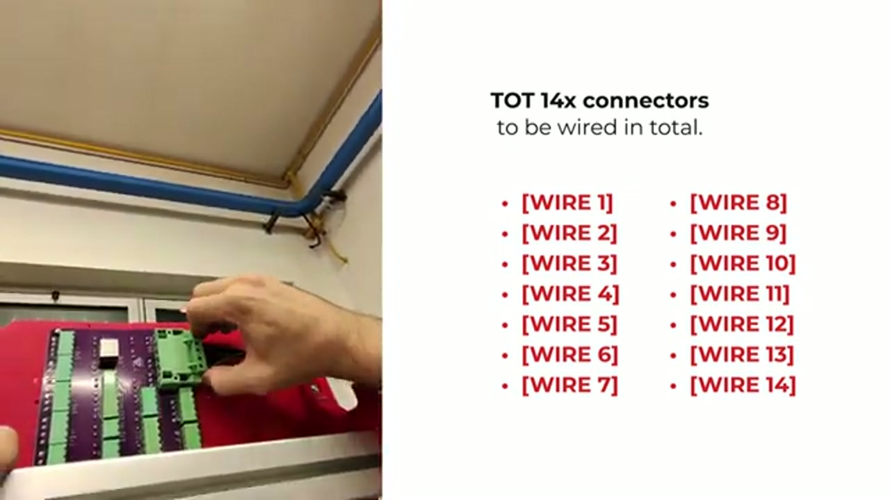
Extruder breakout (behind the extruder)
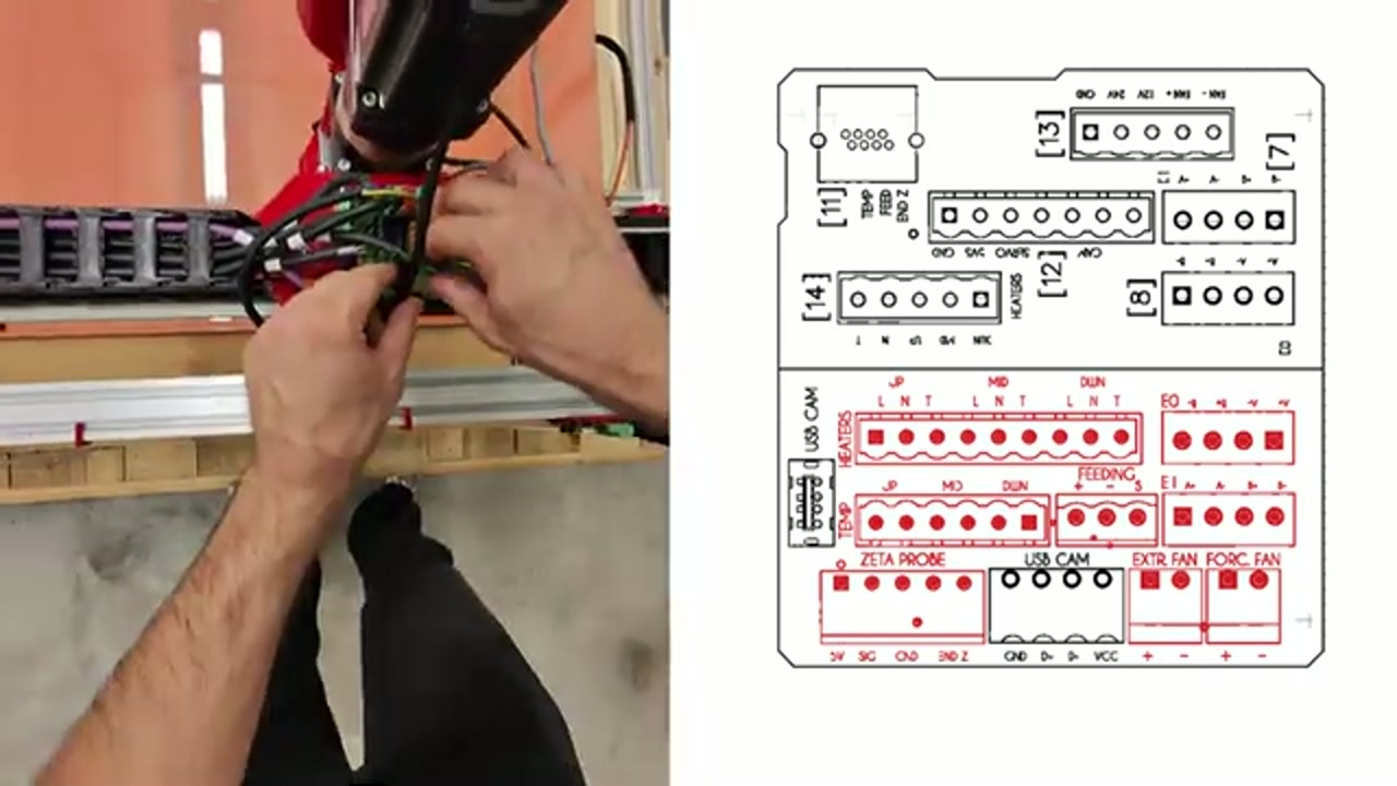
Section titled “Extruder breakout (behind the extruder)”The extruder breakout carries the following extruder-assembly connections:
| Label | Function | Notes |
|---|---|---|
| UP | Feeding Zone heater (top) | L/N/T (Line/Neutral/Temperature) |
| MID | Melting Zone heater (middle) | L/N/T |
| DOWN | Nozzle Zone heater (bottom) | L/N/T |
| TEMP (×3) | Zone thermistors | NTC 100k — read by the Octopus, see Temperature sensor NTC 100k |
| ZETA PROBE | Bed-leveling probe servo + switch | |
| EXTR. FAN | Extruder cooling fan | |
| FORC. FAN | Heatbreaker fans | These cool the heatbreak — not the part-cooling fans |
| FEEDING | Feeding / hopper sensor |
Z motor wiring
Section titled “Z motor wiring”The four Z motors are wired through a fixed circuit already built into the base of the frame: it runs around the perimeter and reaches every corner. The corners are named A, B, C, D.
- The Z motor cables are already mounted in the frame — just check they are in place and connect each motor
- There are 4 motor connections (one per corner) plus one feed cable — WIRE 4 from the panel box — that powers all four Z motors by connecting to the fixed perimeter circuit in the base
- Insert the axes, connect each motor at its corner, then connect WIRE 4 to the base circuit
Probe and fan wiring — at the extruder, not the panel box
Section titled “Probe and fan wiring — at the extruder, not the panel box”When wiring the fans, do not confuse the heatbreaker fans (FORC. FAN) with the part-cooling fans — they are different fans. (A quick check: the part-cooling fans around the nozzle ring behave differently from the heatbreaker fans when the printer is idle.)
Power supply connection
Section titled “Power supply connection”The 24V PSU lives in the power box and feeds the electronics. The main mains power reaches the Panel Box through WIRE 1 (POWER). See Power supply 24V for PSU specifications and how the power box is fed (two switches: main + bed).
Extruder board cover (step 4.4 S35)
Section titled “Extruder board cover (step 4.4 S35)”After completing all extruder wiring, the extruder_board is covered with the S35 cover and secured with V04 x2 (M5x18 CIL) screws. 1 operator, 5 min.
Components list
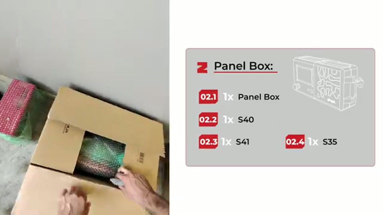
Section titled “Components list”The Panel Box assembly kit includes:
| Code | Item | Qty |
|---|---|---|
| 02.1 | Panel Box (main unit) | 1x |
| 02.2 | S40 screws | 1x |
| 02.3 | S41 screws | 1x |
| 02.4 | S35 screws (cover plate) | 1x |
Assembly position
Section titled “Assembly position”The Panel Box (also called “Control Panel” in the manual, step 3.1) is mounted on the upper frame, secured with M6X20 CIL screws (x2) and Hammer Nuts M6 (x2) that slide into the frame T-slot.
Opening the Panel Box
Section titled “Opening the Panel Box”To access internal components (Raspberry Pi, extruder_board, fuses):
- Locate the two hex screws near the display
- Remove both screws
- Gently swing the Panel Box open — it is also held by internal clips
- Do not force it: if resistance is felt, check that both screws are fully removed first
- Be careful not to strain the ribbon cables and wiring harnesses as you open the panel