
Frame
The G1 is built on a welded and bolted aluminum frame that provides structural rigidity for the gantry, bed, and extruder assembly. Frame squareness directly affects print quality — a racked frame produces layer shifts and dimensional errors even with well-tuned belts.
Structure
Section titled “Structure”- Material: aluminum extrusion profiles + welded plates
- The frame sits on aluminum feet (already mounted under the bottom strips) — no base pallet required
- Corner brackets provide rigidity at all joints
Printed parts
Section titled “Printed parts”The structural printed components on the G1 (brackets, mounts, corner pieces) are made from a PC-PETG blend. This is relevant if you need to print replacement parts — use the same blend or another high-temperature material (not PLA or standard PETG alone) to match the originals. Contact Ginger Additive support for the correct STL files and material recommendations.
Assembly overview (from official manual)
Section titled “Assembly overview (from official manual)”The G1 arrives in a 170 × 170 × 65 cm pallettised wooden crate. Assembly sequence:
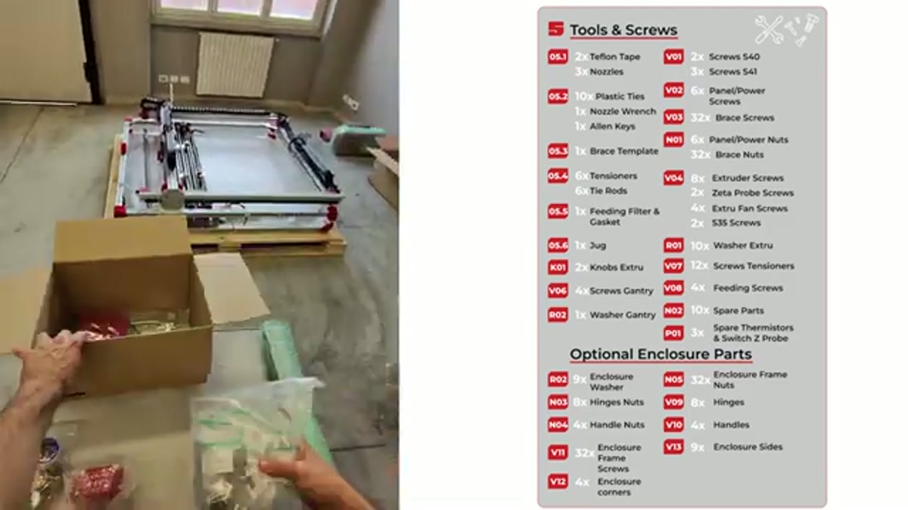
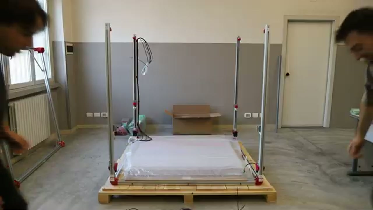
- Lower frame (step 1.1) — pull from crate (step 1.1.1), place on ground (step 1.1.2); can remain on the wooden platform during assembly; pay attention to FRONT label; 2 operators, 5 min
- Zeta axis (step 1.2) — check axle couplings at proper angles (step 1.2.1) before inserting all 4 axes into corners (step 1.2.2); axes interlock in the corner angle; 4 Z axes labeled A, B, C, D; parts needed: 8.1 (x1 set); 2 operators, 5 min
- Gantry (step 1.3) — pull from box, place into carriages and secure; uses V06 M8X25 CIL screws (x4, already on gantry); 4-step install: align with plates, lean with screws, insert second screws, tighten; 2 operators, 15 min
- Upper frame (step 1.4) — pull from box, place over axes paying attention to couplings at all 4 corners A, B, C, D; upper frame is part code 9.2; note the gantry attachment plate-and-screw assembly must look correct; 2 operators, 5 min
- Power chain (step 1.4B) — remove ONLY the WHITE zip ties (leave colored ones); hang chain on hooks, screw to upper frame (step 1.4B.2 position 1) then gantry (position 2) using M6X20 CIL (x2, already in the chain); 1 operator, 10 min
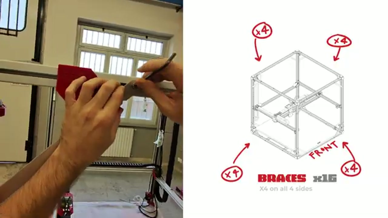
- Angle braces (step 1.5) — 16 braces, 4 per side (14x Brace + 2x Short Brace); use M6X18 SVA (V03) x32 + Hammer Nuts (M01) x32 — two screws and two nuts per brace; position structure parallel and tangent to bracket cut; short braces go at rear right so chain does not rub against them
-
If you bought the enclosure add-on, skip the tensioner step for now — the video says so explicitly at 13:59. It gets done after the enclosure panels instead, and doing it twice means undoing it once
-
Remove the transport spacers — the video flags this in capitals at 2:55: spacers hold the moving parts still during shipping and must come out before the machine ever moves. Check around gantry and carriages
-
Check the frame is securely fitted (video, 3:30) before loading it — every corner coupling seated
- Sort the screw bags (video, 3:50) — the bags are labelled by part code (V03, M01…); sorting them first is what makes the counts checkable
- Frame tensioners (step 1.6) — skip if enclosure add-on ordered (do later, after mounting enclosure panels at step 5.3.4); uses V07 M8X50 CIL (x12), Tensor cod. 05.1; position tensioners (step 1.6.2), screw into angle brackets (step 1.6.3), tighten QS metal cable; 2 operators, 10 min
Squareness check
Section titled “Squareness check”If you suspect the frame is racked (after shipping, relocation, or a collision):
- Check the QS tensioner cable diagonals — with the tensioners (step 1.6) correctly set, each cable measures 209.5 mm from the centre of one S01 screw to the centre of the opposite one, on the diagonal. Both diagonals must read 209.5 mm; if they differ, the frame is racked.
- If the QS diagonals are unequal: loosen the tensioners, realign the frame, re-tension — both diagonals must reach 209.5 mm symmetrically.
- As a secondary check, measure the diagonal of the frame opening itself (corner to corner); both frame diagonals should match within ±2 mm.
- The red corner pieces are part S01 — they are the reference the QS measurement is taken from.
Frame bolts
Section titled “Frame bolts”Over time (especially after shipping or moving), frame bolts can loosen. Symptoms:
- Unusual vibration or noise during printing
- Layer shift that cannot be fixed by belt tensioning
- Frame visibly flexing during fast moves
Check and retighten all accessible frame bolts annually, or after any relocation.
Placement requirements
Section titled “Placement requirements”- Flat, stable surface — the frame has no leveling feet; surface must be level
- Clearance: about 50 cm — a little more if you can — on the front and on the left side, where the display is, so you can work around the machine. The rear and right side can go closer to a wall
- Keep the pellet bucket close (shorter tube = better suction)